Features
Recirc
Research
Evaluation of a velocity assist inlet for improvement of hydrodynamics in dual-drain fish tanks
February 22, 2023 By Brian Vinci, Khurram Shahzad, and Curtis Crouse
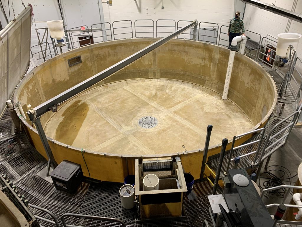 Hydro velocity assist tank (Photo: Freshwater Institute)
 One type of fish tank used in recirculating aquaculture systems (RAS) is the Cornell-style dual-drain circular tank. Cornell-style dual-drain fish tanks have two drains: a bottom centre drain and an elevated sidewall drain.
Cornell-style dual-drain tanks are advantageous because the rotational velocity caused by the inlet water injection creates a self-cleaning effect. In operation, a Cornell-style dual drain tank functions as a swirl separator with waste solids collecting at the tank centre and flowing out of the bottom centre drain. These fish tanks also provide a relatively uniform environment for the fish, with minimal gradients in dissolved oxygen (Davidson & Summerfelt, 2004).
In a typical Cornell-style dual-drain circular tank, the injection of treated RAS water causes a rotational velocity highest at the tank perimeter with decreasing velocity toward the tank centre. Recent research indicates that increased water velocities provide performance benefits for Atlantic salmon post-smolts raised in fish tanks (Timmerhaus et al., 2021).
To achieve these benefits, an additional inlet can be installed on a separate pumped loop that removes water from the fish tank and re-injects it to increase water velocities. This internally pumped “velocity assist” inlet aims to increase water velocities available to larger post-smolt and harvest-size salmon in commercial-scale Cornell-style dual drain circular fish tanks.
This study sought to evaluate the effect of the velocity assist technique by testing combinations of three different water flow rates and three different nozzle headloss configurations for a velocity assist inlet in a semi-commercial scale RAS used for land-based grow-out of Atlantic salmon with the intent of determining optimal combinations for increasing water velocities at minimum energy.
Materials and methods
The velocity assist technique was empirically evaluated by adding a pumped velocity assist loop with an adjustable inlet in a 150 m3 Cornell-style dual drain circular tank that is part of the semi-commercial scale RAS at the Freshwater Institute (USA). Empirical water velocity sampling of tank currents was carried out for all combinations of the following: ~30% of the main flow as velocity assist flow (1136 lpm), ~50% of the main flow as velocity assist flow (2271 lpm), ~60% of the main flow as velocity assist flow (2763 lpm) and low (0.14 bar), medium (0.33 bar), high (0.56 bar) velocity assist inlet nozzle headloss. Water flow was adjusted by changing the number of pumps operating and adjusting a control valve. Nozzle headloss was adjusted by changing the number of 2.54 cm openings on the inlet.
Water velocity measurements were collected using a SonTek Argonaut-ADV 3-axis Doppler velocity meter at three depths across two cross-sections (Line A and Line B) once steady-state conditions were achieved for each combination of flow and headloss (Figure 1). Water velocities were also characterized for the tank without the velocity assist inlet in operation.

Figure 1. Locations of water velocity measurements in the 150 m3 Cornell-style dual drain circular tank that is part of the semi-commercial RAS at the Freshwater Institute facility (USA).
Results
Water velocity data collected across all conditions ranged from 2 cm/s to 64 cm/s, with the lowest velocities at the tank centre and the highest velocities at the tank perimeter. Data were visualized using intensity plots with the x-axis and y-axis representing the tank cross-section and colour illustrating water velocity. Figure 2 shows the intensity plot for the tank without the velocity assist inlet in operation at the Line B cross-section.
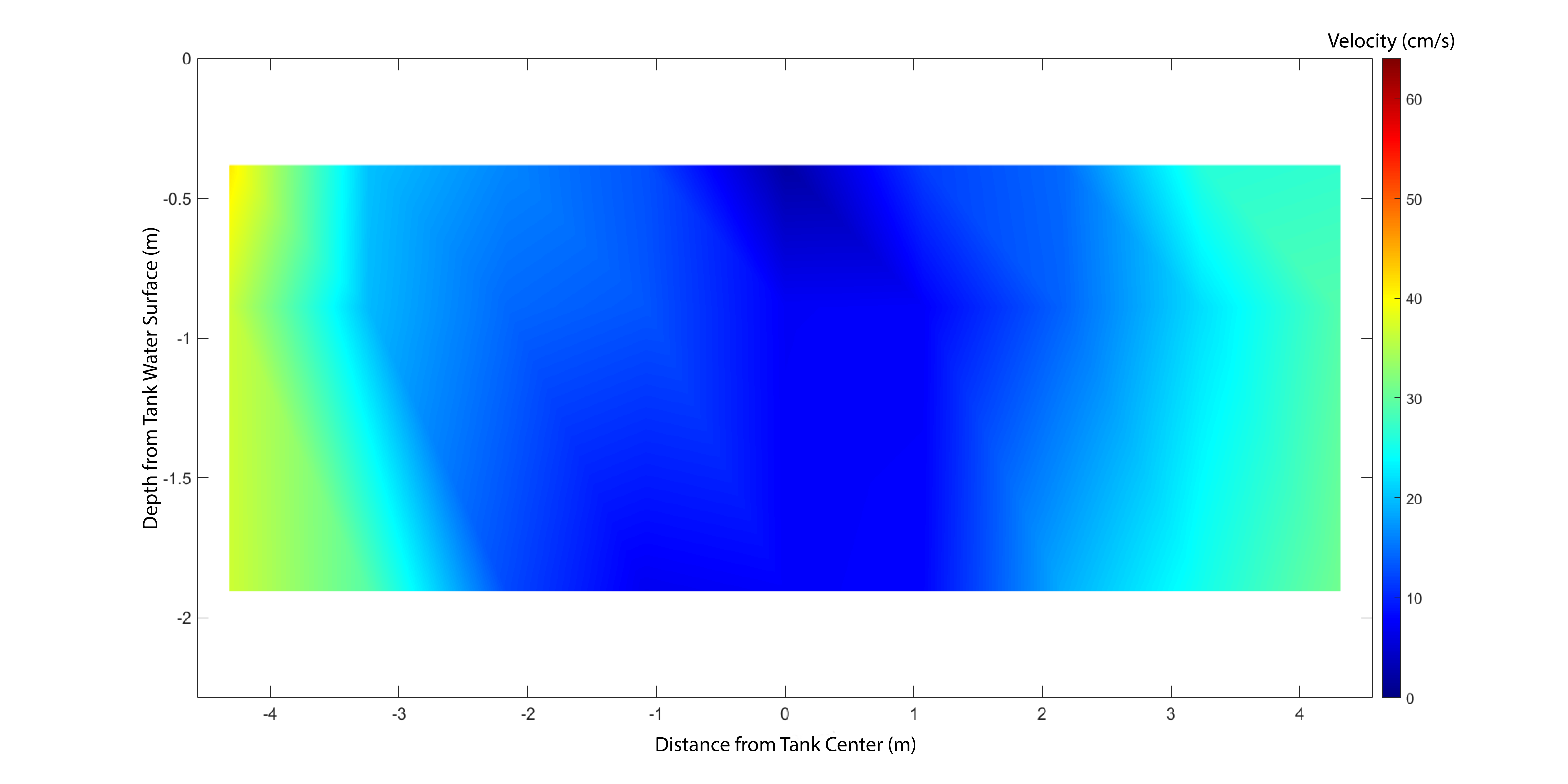
Figure 2. Water velocity intensity plot at one cross-section (Line B) without the velocity assist inlet in operation. (Image: Freshwater Institute)
In general, tank water velocities increased as the velocity assist inlet was operated at increasing flow for the same velocity assist inlet nozzle headloss, as well as for increasing inlet nozzle headloss at the same flow (Figure 3).
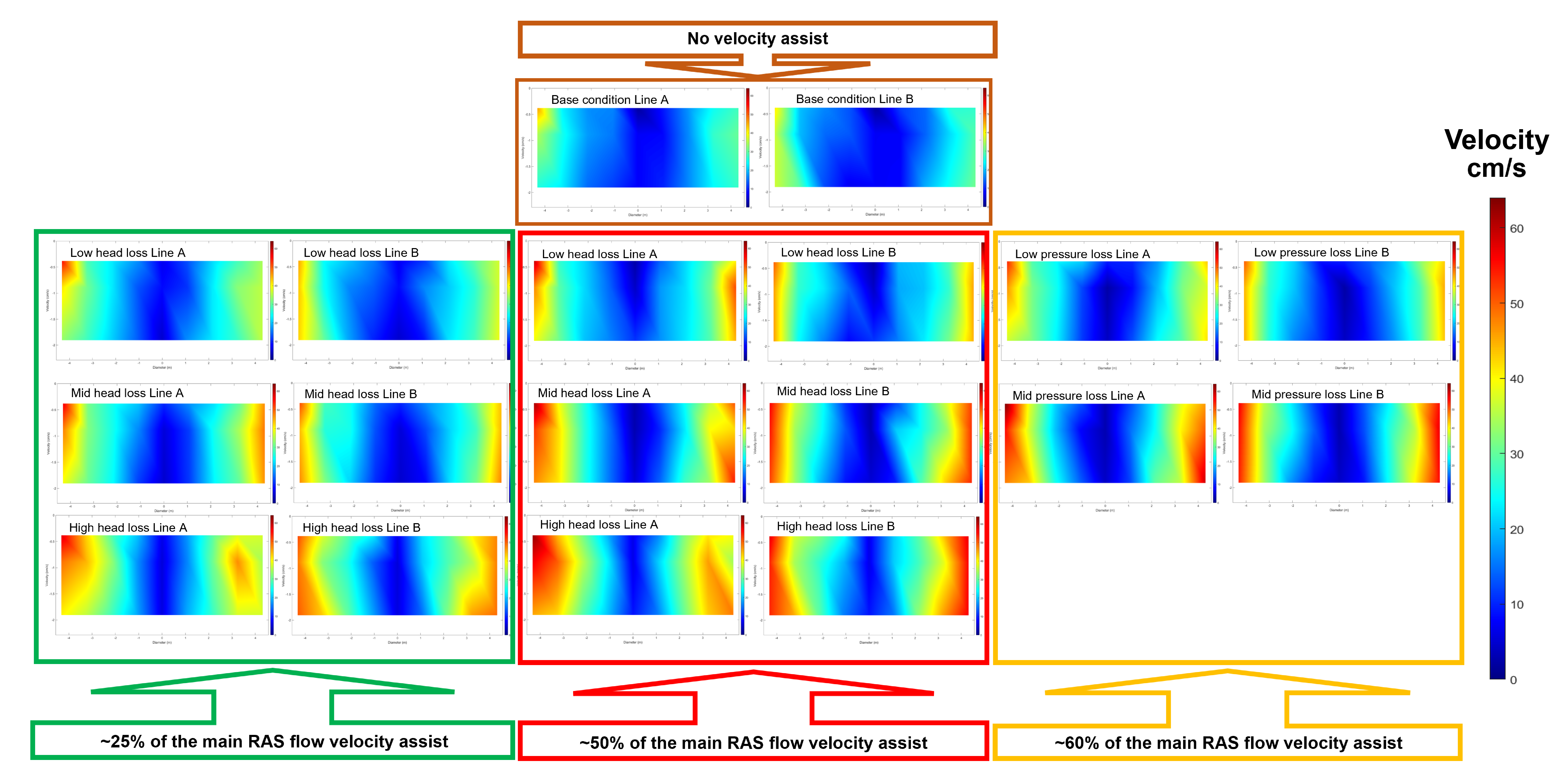
Figure 3. Water velocity intensity plots for all conditions evaluated. (Image: Freshwater Institute)
Operating conditions were ranked according to the number of velocity data points for both cross-sections that fell below a minimum velocity criterion (Table 1). A velocity of greater than 20 cm/s was used as the minimum required to move solids in the water column toward the tank centre drain and promote tank self-cleaning. The ranking indicated that as the velocity assist inlet nozzle headloss increased, the number of data points below the criterion decreased, independent of velocity assist inlet flow. Additionally, the ranking indicated that for the highest velocity assist inlet nozzle headloss, the number of data points below the criterion decreased as velocity assist inlet flow increased.
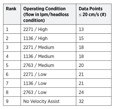
Table 1. Operating conditions ranking according to the number of velocity data points equal to or below 20 cm/s. (Image: Freshwater Institute)
Discussion
In both the data visualization and ranking analysis, the operating condition with the velocity assist inlet at 50% of the main flow as velocity assist flow (2271 lpm) at the highest inlet nozzle headloss provided the highest increase in water velocities over the baseline condition. This operating condition yielded a water velocity range between 40–62 cm/s near the wall region of 1.5–2 m and a smaller region of lower velocities in the tank centre region than other conditions evaluated. Increasing velocity assist inlet flow from 50% to 60% of the main flow as velocity assist flow (2763 lpm) did not result in a better ranking for either low or medium inlet nozzle headloss conditions (the high inlet nozzle headloss condition was not achievable for the highest inlet flow due to equipment limitations). The lack of improvement in fewer data points below the criterion may have been due to the increased turbulence created by the inlet nozzles at the highest flow.
Conclusion
Results indicate that the operation of the velocity assist inlet improved velocity profiles in the 150 m3 Cornell-style dual drain circular tank versus the baseline condition without a velocity assist inlet. Higher velocities were observed throughout the tank with higher velocity assist inlet water flow and nozzle headloss. The use of a velocity assist inlet effectively decouples the control of tank water velocities from the primary inlet flow and allows for more control of rotational velocities. The velocity assist inlet technique is valuable for providing fish with an optimal training regime. It can also achieve a range of optimal velocities for different fish species and sizes.
Acknowledgment
This research was part of the CtrlAQUA SFI, Centre for Closed-Containment Aquaculture, funded by the Research Council of Norway (project #237856/O30) and the CtrlAQUA partners.
References
Davidson, J., & Summerfelt, S. (2004). Solids flushing, mixing, and water velocity profiles within large (10 and 150 m3) circular ‘Cornell-type’ dual-drain tanks. Aquacultural Engineering, 32, 245–271.
Timmerhaus, G., Lazado, C.C., Cabillon, N.A.R., Reiten, B.K.M., and Johansen, L.H. (2021). The optimum velocity for Atlantic salmon post-smolts in RAS is a compromise between muscle growth and fish welfare. Aquaculture, 532, 736076.
Print this page